

Technical insight
How to Charge a Start-Stop Battery and Check Charging Compatibility
Charge AGM/EFB start-stop batteries safely, assess smart charging, and prepare a NaVolt sodium-ion review for fleet evaluation.
Charge a start-stop battery with an automatic charger that supports the installed technology—usually AGM or EFB—and follow the battery and vehicle manufacturer’s instructions. Connect at the specified charging points so the vehicle’s energy-management sensor remains in the intended circuit. Do not choose a voltage from a generic internet chart or use an uncontrolled charger simply because both products say 12 V.
If the battery is damaged, frozen, leaking, unusually hot or emitting a strong odour, stop and arrange professional inspection.
Before charging: identify what is installed
Read the battery label and record:
- AGM, EFB or another technology;
- nominal voltage;
- capacity and model;
- manufacturer charging instructions;
- battery location and ventilation requirements;
- vehicle-approved charging connection points.
AGM and EFB are both lead-acid designs, but they are not the same construction. A charger may use different logic for each. Gel mode is not a substitute for AGM mode unless the charger manufacturer explicitly says so.
Use the vehicle’s charging points
On many start-stop vehicles, the negative battery cable includes a current sensor. Connecting a charger directly in a way that bypasses that sensor can prevent the energy-management system from registering the charge correctly.
The owner manual may specify a positive jump or charge terminal and a chassis ground point. Use those points. If the battery must be removed or disconnected, follow the manufacturer’s procedure for maintaining settings, isolating circuits and reconnecting safely.
How to charge a start-stop battery: a practical charging sequence
1. Prepare the area
Work in a ventilated, dry location away from flame, sparks and smoking. Switch off the vehicle and charger before making connections. Wear the protective equipment specified by the battery and charger manufacturers.
2. Inspect and identify polarity
Check the case, terminals, cable lugs and hold-down. Confirm positive and negative markings. Never guess based on cable colour alone.
3. Connect in the prescribed order
Follow the charger and vehicle instructions. Common practice is to connect the positive lead to the approved positive point and the negative lead to the approved ground point, then power the charger. The exact procedure for the vehicle takes precedence.
4. Select the correct programme
Choose the programme for AGM, EFB or the specific start-stop battery. Enter capacity if the charger requires it. Temperature-compensated charging is useful when the product supports it because battery charging behaviour changes with temperature.
5. Let the automatic cycle finish
Do not repeatedly interrupt the cycle to chase a particular display voltage. A quality charger may use several stages for assessment, bulk charging, absorption and maintenance. Its manual explains the indicators.
6. Disconnect safely
Switch off or unplug the charger as instructed before removing leads. Disconnect in the order specified by the charger and vehicle manufacturer. Refit terminal covers and verify that tools have been removed.
Why a single voltage reading cannot establish compatibility
The correct target for any battery depends on its technology, product design, operating temperature and the charging stage at the moment of measurement. Even within AGM, manufacturers can specify different limits. Quoting one universal voltage risks undercharging one product and overcharging another.
In a vehicle, the alternator or DC-DC converter may intentionally vary its output. A momentary voltage reading captured with a multimeter is not the same as a charger set point, and a specification-sheet value is not automatically the vehicle’s required alternator output.
For any battery replacement evaluation, the buyer must distinguish between three distinct charging scenarios:
- Automatic workshop or maintenance charger selection — the device selects a programme for the battery technology present.
- In-vehicle charging by the alternator, DC-DC converter, smart-charge strategy or regenerative-energy management — the vehicle controls voltage and current based on sensor data, temperature and operating state.
- Engineering review of a specific product’s charge specification against the vehicle’s actual charging profile — requires a documented evidence package, not a single field value.
Understanding the vehicle charging architecture
Modern vehicle charging systems can use a combination of sensors, communication protocols and control logic. According to HELLA’s official alternator-regulator guidance, the charging control in a modern vehicle may vary with battery type, battery temperature, the electrical load currently active, the operating state of the engine and signals from an intelligent battery sensor (IBS) that communicates data such as voltage, current and temperature via a LIN (Local Interconnect Network) bus.
These variables mean that a vehicle may deliberately run its alternator output at different voltage levels at different times. The charging system may also require a battery-registration or adaptation step after a replacement so the energy-management controller can apply the correct charging logic for the new battery.
HELLA’s start-stop charging-system overview further shows how an IBS, engine-control module and LIN-connected regulator can work together to request charging voltage and manage the vehicle electrical system.
Key implications for any battery replacement evaluation:
- A single voltage measurement taken at the battery terminals while the engine is running does not confirm that the vehicle can charge a replacement battery to its required voltage and current limits.
- The presence or absence of an IBS and the type of charging control (conventional alternator with fixed regulator, smart alternator with variable set point, or DC-DC converter) must be identified for the specific vehicle.
- Any battery registration, coding or adaptation procedure required by the vehicle manufacturer must be recorded as part of the evaluation.
Compatibility evidence checklist
When evaluating a starter-battery replacement — whether lead-acid, AGM, EFB or an alternative chemistry — collect the following data for each target vehicle or application. This package allows an engineering team to review compatibility against the candidate battery’s controlled specification.
| Evidence item | Description |
|---|---|
| Vehicle/application and role | Make, model, model year, market region, and the battery’s role (engine starting, auxiliary, dual-battery system) |
| Installed battery technology | AGM, EFB, flooded lead-acid or other; CCA rating, capacity, group size |
| Measured voltage range | Minimum and maximum voltage at the battery terminals across representative driving conditions (idle, cruise, regenerative braking, electrical load on/off) |
| Charge-current behaviour (if available) | Observed current during bulk phase, sustained current during extended drive |
| Alternator/DC-DC architecture | Conventional alternator with fixed voltage regulator, smart alternator with variable set point, or DC-DC converter; nominal system voltage (12 V or 24 V) |
| Intelligent battery sensor | IBS present or absent; communication type (LIN or other) |
| Registration/adaptation requirement | Battery registration, coding or adaptation step required by the vehicle OEM after replacement |
| Intended replacement model | Candidate battery model and its controlled charge voltage and current limits |
| Terminal, mounting and installation constraints | Terminal type and orientation, hold-down system, tray dimensions, clearance for vent tubes (if applicable) |
Do not assume that a vehicle that runs at one voltage condition can supply a different voltage on demand. The evidence package must be reviewed together, not field by field in isolation.
Controlled NaVolt charge-field table
The current NaVolt 12 V start-stop and starter-battery range lists a charge voltage of 15.8 V and a charge-temperature range of −20 to 45 °C for all models. The maximum continuous charge current varies by physical design:
| NaVolt model | Max continuous charge current |
|---|---|
| B19-12V-500 | ≤ 10 A |
| B24-12V-660 | ≤ 15 A |
| H4-12V-400 | ≤ 15 A |
| D23-12V-850 | ≤ 20 A |
| D26-12V-850 | ≤ 20 A |
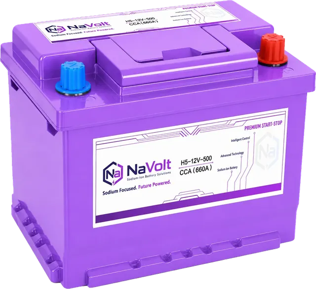
| H5-12V-500 | ≤ 20 A |
| D31-12V-1000 | ≤ 25 A |
| H6-12V-600 | ≤ 25 A |
| H7-12V-750 | ≤ 30 A |
| H8-12V-840 | ≤ 35 A |
| H9-12V-900 | ≤ 40 A |
Important: 15.8 V is a product specification field — it defines the charge voltage that the product is designed to receive under its controlled charging method. It is not a universal required alternator output and it is not proof of drop-in compatibility with any vehicle. The vehicle’s actual charging profile must be compared against the complete specification (voltage, current and temperature limits) by the manufacturer’s engineering team.
When charging does not solve the problem
If the charger will not accept the battery, repeatedly reports a fault, or the battery becomes low again soon after a complete cycle, investigate:
- battery state of health;
- loose or corroded connections;
- alternator or DC-DC charging performance;
- excessive key-off current;
- repeated short-trip duty;
- incorrect battery technology or missing registration;
- an internal battery fault.
Use the start-stop battery testing procedure before authorising a replacement.
Charging a battery outside the vehicle
Removal may be appropriate for some service procedures, but it can reset vehicle systems or require memory support. Some battery locations also need special venting or access steps. Follow the workshop manual.
Secure the battery upright on a stable surface unless the manufacturer approves another orientation. Do not charge a frozen battery. Allow temperature to normalise and have it inspected for damage.
Assembling an evidence package for sodium-ion sample review
For customers evaluating NaVolt sodium-ion samples, the same charging-architecture data described above forms the basis of an engineering compatibility review. Fleet and OEM buyers are encouraged to collect the information from the evidence checklist for each target vehicle and submit it together with the intended NaVolt model for a model-specific application review.
The controlled charge fields in the NaVolt specification sheets — 15.8 V charge voltage, model-specific maximum charge currents, and −20 to 45 °C charge-temperature range — are the current reference values that engineering teams use during platform review. These values must be interpreted within the product’s charging method, not extracted as isolated requirements.
Use the fleet sample-validation checklist to structure the trial, then contact the NaVolt engineering team with the vehicle data pack and candidate model reference.
Frequently asked questions
Can I use a normal charger on an AGM start-stop battery?
Only if the charger manufacturer approves it for AGM and its programme matches the battery specification. An older uncontrolled charger may overcharge the battery.
Should I disconnect the battery before charging?
Not always. Many vehicles provide approved in-vehicle charging points. Follow the owner or workshop manual because disconnection can affect vehicle electronics and battery monitoring.
How long does charging take?
It depends on battery capacity, starting SOC, charger current, temperature and battery condition. Use the charger’s completion indication rather than a fixed time estimate.
Why is start-stop still unavailable after charging?
The battery may need testing, registration or vehicle adaptation, or another operating condition may be inhibiting start-stop. Check diagnostic messages and the vehicle manual.
Does a higher alternator voltage guarantee compatibility with a different battery type?
No. The alternator’s output is determined by the voltage regulator and the vehicle’s energy-management logic, not by the battery’s specification-sheet values. Compatibility depends on the full charging profile — voltage, current and temperature — not a single field.
What information should I prepare for a sodium-ion sample review?
Collect the evidence from the compatibility checklist above: vehicle details, installed battery, measured voltage and current behaviour, charging architecture, IBS type, registration requirements, and the intended NaVolt model. Submit this data pack to NaVolt engineering for a model-specific review.
Sources
- HELLA, “Checking an alternator regulator”
- HELLA, “Service work on the charging system”
- CTEK CT5 START/STOP charger information
- VARTA: Start-stop technology
For sodium-ion sample charging and vehicle integration, request a model-specific specification and application review from NaVolt.